A number of discontinuities can occur in welding. Porosity is among the more common ones, and it can appear on a wide range of materials – from carbon and stainless steel to aluminum and more.
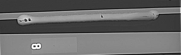
Porosity results from gases such as hydrogen, oxygen and nitrogen becoming trapped in the molten weld pool as it solidifies. It can sometimes be found on the surface of the weld by visual inspection, but more often, porosity occurs in the subsurface of the weld and is identified by nondestructive testing, ultrasonic testing or X-ray.
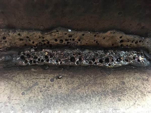
While porosity does not typically cause weld failures, it can still reduce weld quality. Porosity decreases weld ductility and toughness and may also lower the weld’s tensile strength. As a result, even if it does not lead directly to an issue like cracking, excessive porosity can cause a weld to fall outside the required specifications for a given part.
In many instances, operators may suspect a faulty filler metal or contaminated shielding gas as the cause of porosity. However, it most often results from other issues. Fortunately, with some training, it is relatively simple to identify the common causes and apply best practices to resolve them. This also allows fabrication shops to spend less time reworking welds and more time getting parts out the door.
Material condition
Contamination on the base material is a common cause of porosity occurring on the surface of welds. It can be caused by oil, grease, rust, paint, millscale or cutting fluid. To prevent this issue, it is important to always have a clean surface before welding.
For carbon steel, simply wipe down the material with a clean cloth to remove oil, grease or cutting fluid. Be sure to take care that there is no pooling of these contaminants that could be pulled into the joint during welding.
When working with aluminum, clean the surface with a clean cloth and acetone. Remove rust, paint and millscale with a grinding wheel or flap disc. While this step requires an investment in a grinder and abrasives and so may be tempting to skip, it is still an important step. A clean surface provides higher quality welds and minimizes costly and time-consuming rework.
Moisture care
Moisture on the filler metal or base material is another cause of porosity. Always store welding wire in a cool, dry area, according to the manufacturer’s instructions. If the storage area is a much cooler temperature than the area where welding will take place, bring the wire in its original packaging into that area to acclimate for 24 hours before use. Doing so allows any resulting condensation (from moving from a cold to warmer area) to evaporate while the wire is protected in the package.
Never bake a welding wire to remove moisture. Unlike stick electrodes that are stored in ovens to prevent moisture pickup, filler metals often used in fabrication shops such as solid, metal-cored and gas-shielded flux-cored wire are not designed for this treatment. Heat can degrade the feeding lubricant or damage plastic/fiber spools.
Take similar precautions with base materials to avoid introducing moisture into the welds. When possible, store the material in a dry area. If stored outside, wipe the material of any water or snow and allow it to acclimate to the temperature of the shop floor before welding.
The 24-hour rule is good to follow here, too. For aluminum, wiping the surface with acetone removes moisture as well as any contamination.
Shielding gas flow
Inadequate shielding gas flow with GMAW or gas-shielded flux-cored welding can lead to porosity and can be caused by several issues.
Setting the flow too low does not allow the shielding gas to protect the molten weld pool. When short-circuit welding with solid wire, a typical gas flow rate is around 20 cubic feet per hour (CFH), whereas a gas-shielded flux-cored wire requires a higher rate, around 35 to 45 CFH. For exact CFH, always consult the filler metal specifications sheet for the manufacturer’s recommended flow rate.
Welding in drafty areas can also disrupt shielding gas flow and prevent it from protecting the weld pool. Utilize wind blocks and increase the CFH, as needed, while staying within recommended flow rates; flow that is too high can create turbulence with the gas and cause issues, as well.
Leaks in the gas hose or bad connections at the cylinder or the welding gun can also lead to poor shielding gas coverage and porosity. Check for any nicks in the hose and for loose connections, replacing the hose as necessary and tightening connections.

If the shop places its gas cylinders a fair distance from the welding station, it is possible to lose flow rate as the shielding gas travels through the hose to the welding gun. Use a flow gauge at the nozzle to verify that the flow rate is the same as what is set at the gas cylinder. Increase the CFH as needed to achieve the correct flow rate.
Using too small a nozzle size can impede shielding gas flow, as can a clogged nozzle. Instead, use a larger nozzle that is still able to provide access to the weld joint.
Never hammer the nozzle on a hard surface to clear spatter, as it can misshape the nozzle and lead to poor shielding gas coverage. Use a pair of welding pliers to remove any spatter buildup. When using anti-spatter compound, only dip the front end of the nozzle to avoid clogging the ports inside and impeding gas flow.
Incorrect technique
Travel speeds that are too fast or too slow when welding can negatively affect shielding gas coverage of the weld pool, which again can lead to porosity. When traveling too fast, the welding operator essentially “outruns” the weld pool, while traveling too slow increases the size of the weld pool beyond what the shielding gas can cover. The recommended travel speed depends on the welding process.
For example, short-circuit GMAW is slower at around 6 to 10 ipm, while metal-cored wire, which has higher deposition rates, is faster at approximately 12 to 25 ipm or higher. The key, regardless of the welding process, is to maintain a pace that keeps the arc on the leading edge of the weld pool.
Another cause of porosity is welding at too steep an angle when using a push technique for aluminum. It results in too much shielding gas in front of the weld pool and inadequate coverage. Correct this by keeping the nozzle at an angle of 10 to 15 degrees.
Likewise, using an incorrect contact-tip-to-work distance (CTWD) can also lead to porosity. When welding with solid wire, the CTWD should be around 1/2 in. to 5/8 in., while gas-shielded flux-cored and metal-cored wire typically operate at a CTWD of 3/4 in. to 1 in. Always consult the filler metal manufacturer’s specification sheet for exact details.
While a common discontinuity, porosity does not have to slow down a welding operation. Training welding operators on how to properly assess base material conditions, how to store and handle filler metals and base materials, and how to address potential shielding gas flow issues is key to resolving the issue of porosity, as is using the correct technique specific to the type of welding work being done. Following best practices can also go a long way in preventing the problem in the first place and helping to avoid unnecessary downtime for rework.
Thanks for reading this article about how to keep porosity at bay. To learn more about Hobart filler metals and how they play into successful welding processes, you’ve come to the right place. Techgen Media has been collaborating with Hobart for more than a decade.